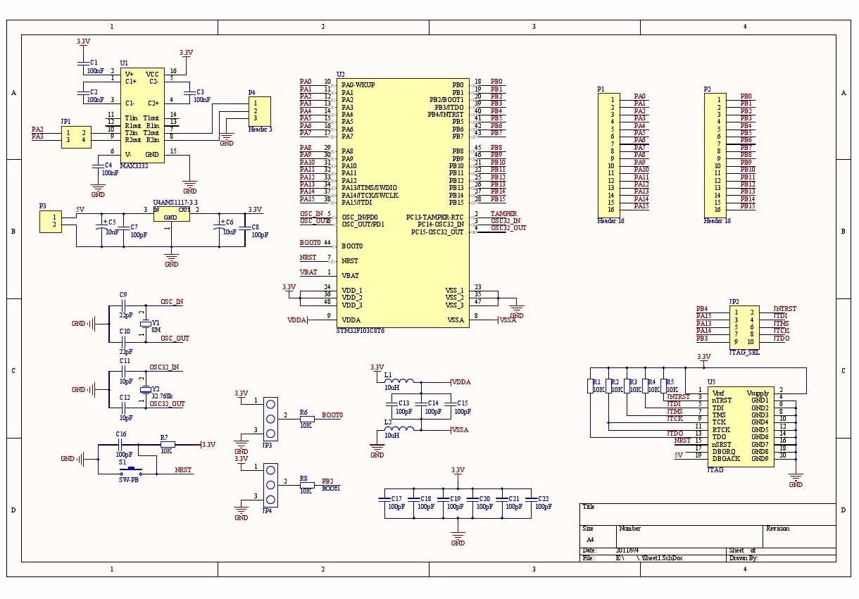


I have not had issues with the usb connector (as silly as it is usb b connectors are cheap and easy to solder, waayy overkill but cheap and easy) D+/D- direct to the part and then an AP2112 to get 3.3 out of the 5V from the usb connector. No external termination series resistors are required on USB_DP (D+) and USB_DM (D-) the matching impedance is already included in the embedded driver. To be compliant with the USB 2.0 full-speed electrical specification, the USBDP (D+) pin should be pulled up with a 1.5 kΩ resistor to a 3.0-to-3.6 V voltage range. power it from the pins and manipulate boot0 and reset (or power on) to put it into the bootloader mode then use the uart interface to program the part (simple protocol, the different stm32s use different features of the protocol but still easy to implement or probably find an existing tool). for about a buck a board at oshpark you can make a breakout board, the part, and header pins, done. So depending on what your real goal is, it takes almost nothing to get the part to work.


 0 kommentar(er)
